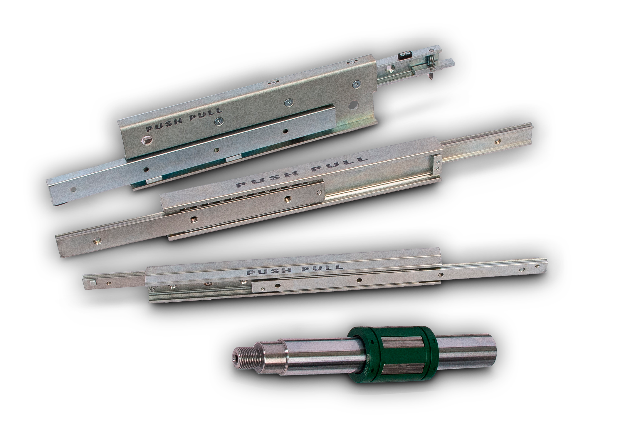
Push Pull
linear and telescopic guides
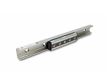
Linear roller, telescopic and Cylindrical guides

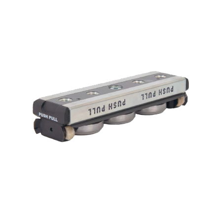
With two types of C-profile, LR and LUR, and a steel roller
slider, the system is highly rigid and
suitable for the most demanding applications in terms of
load capacity, dynamics and
environmental conditions.
The guide profiles are made of zinc galvanized cold-drawn
carbon steel. Raceways can be heat
treated and subsequently ground. The LR and LUR profiles
combination can compensate axial
misalignment up to 3.9 mm.
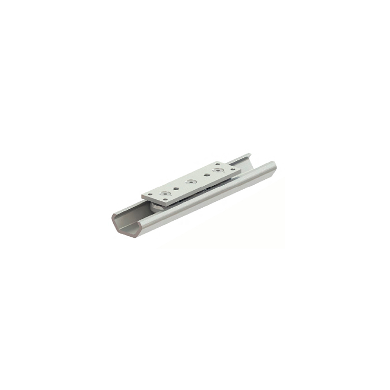
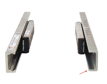
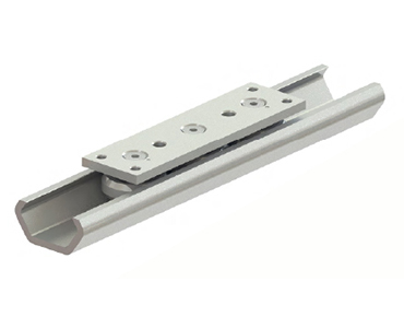
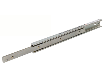
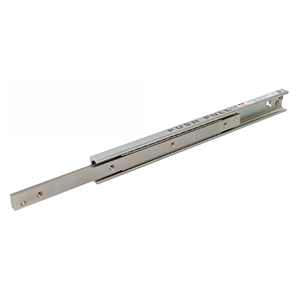
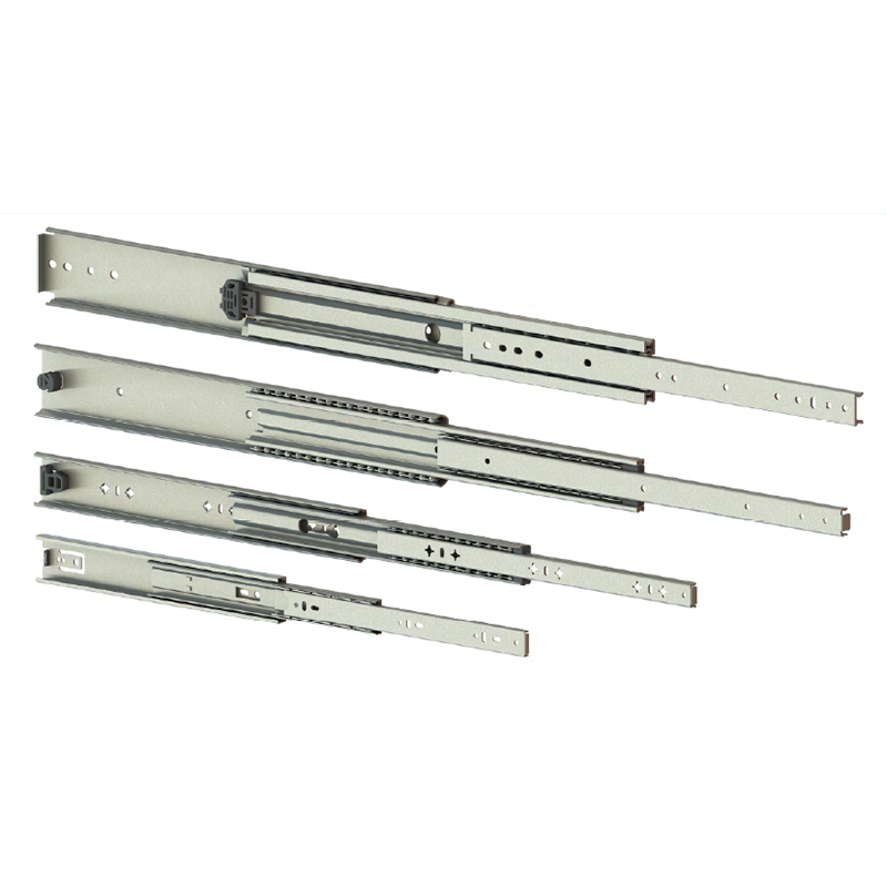
Three roller sliders in zinc plated formed steel profile. This series is designed for applications that require good performance at an affordable price. There are 3 type-sizes in the series, depending on the height of the profile: 20, 30, 45.
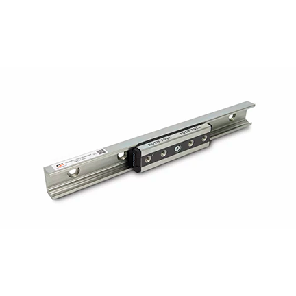
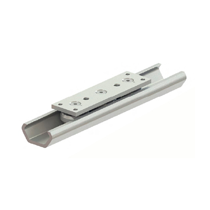
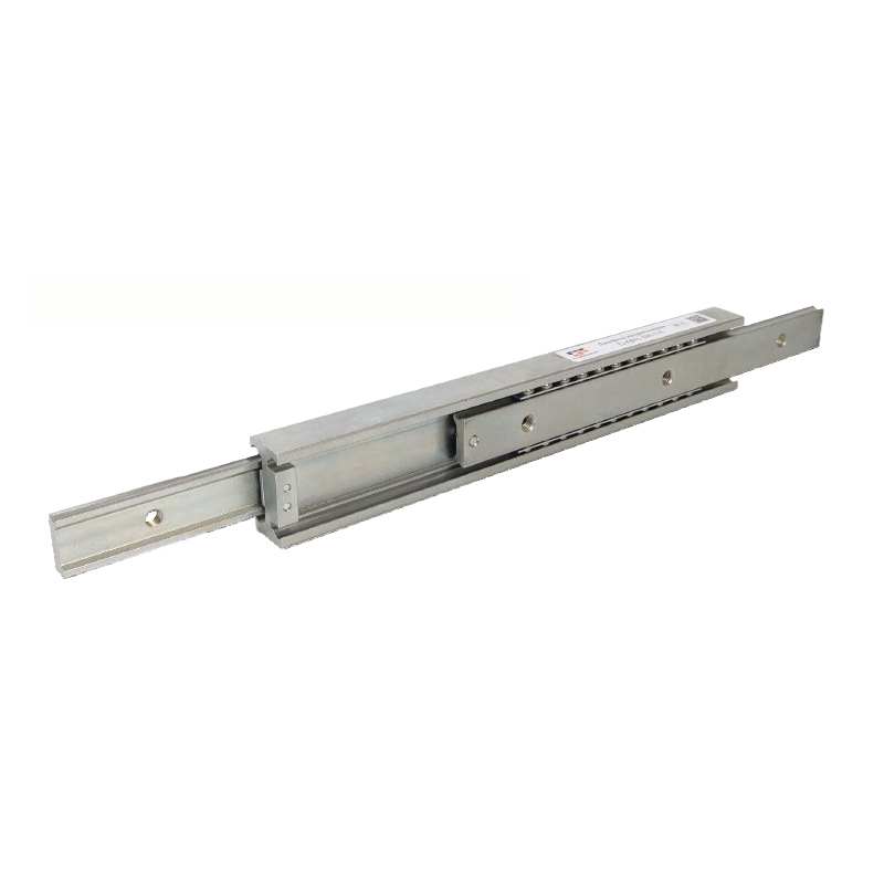
43 size carriages equipped with rollers with double row bearings. Increased load capacity while maintaining overall dimensions with standard 43 size carriages. The reinforced version is designed for guides LR and LUR 43 of standard size COMPACT series.
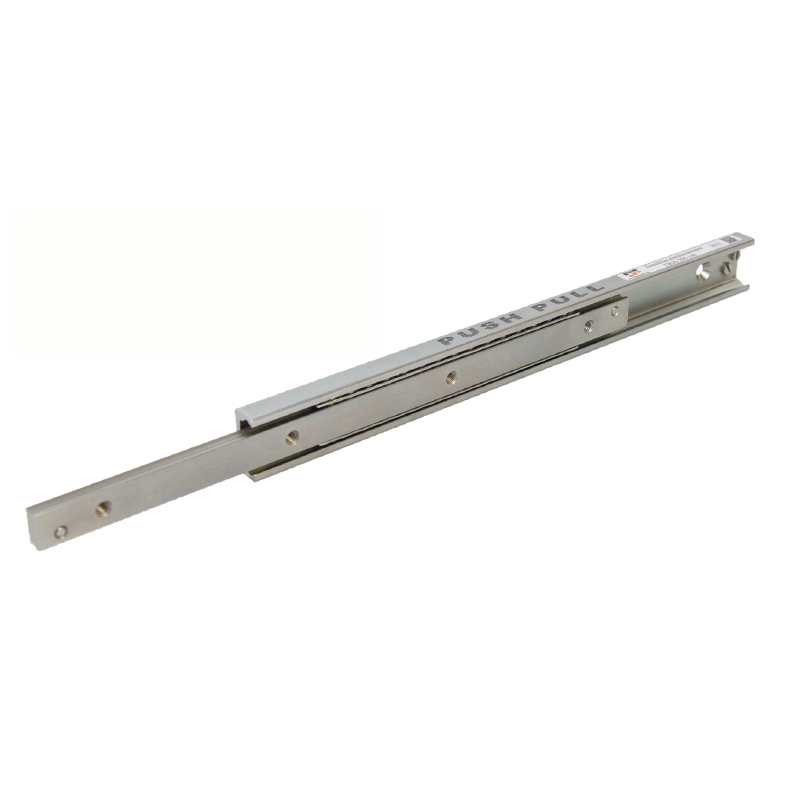
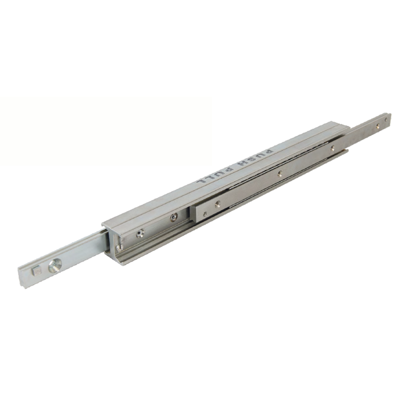
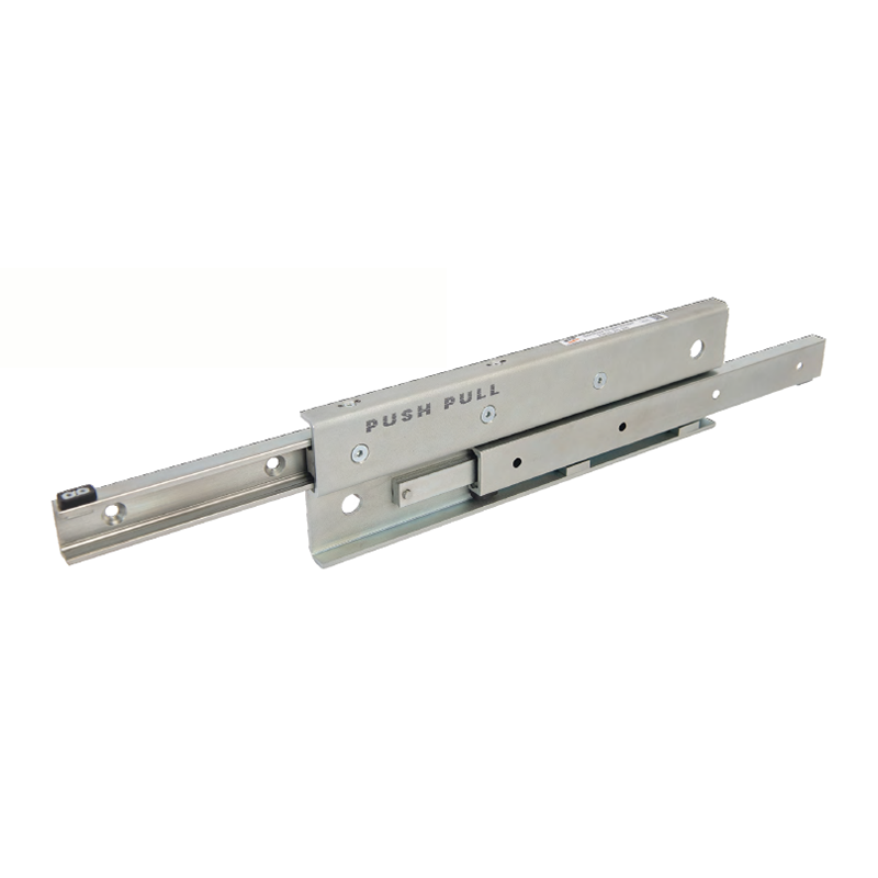
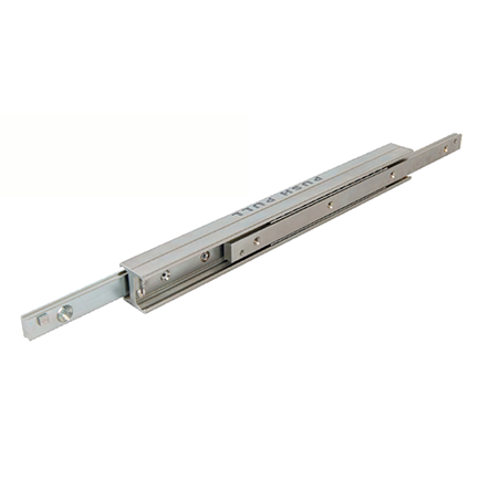

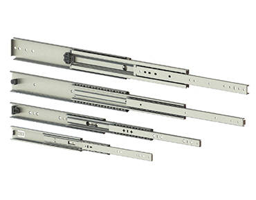
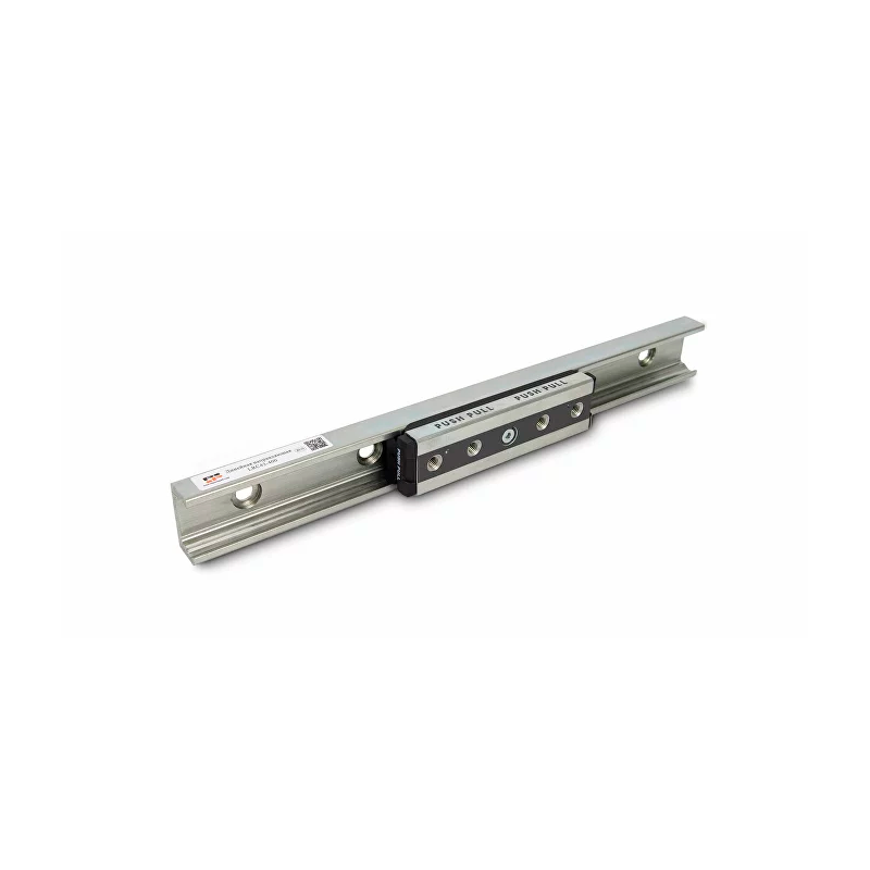
Telescopic guides with full and partial extension are made of cold-drawn steel profile. The variety of shapes of the middle element makes it possible to find the appropriate solution for all applications.
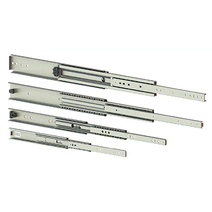
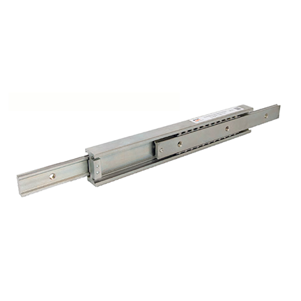
Lightweight telescopic guides with full extension LIGHTSLIDE are made of galvanized sheet steel. Guides are available in four sizes depending on profile height: 45, 53, 71 and 76. Sizes 53 and 76 are available with locking mechanism in open and closed positions. All guides are equipped with a locking device in closed position. Guides construction allows to remove movable slider for separate mounting (except size 76).
| Code | Leigth, mm | Stroke, mm | Load capacity, H | Weight, kg |
| TLSB45-250-260 | 250 | 260 | 400 | 0,38 |
| TLSB45-300-310 | 300 | 310 | 400 | 0,45 |
| TLSB45-350-360 | 350 | 360 | 400 | 0,53 |
| TLSB45-400-410 | 400 | 410 | 450 | 0,61 |
| TLSB45-450-460 | 450 | 460 | 450 | 0,68 |
| TLSB45-500-510 | 500 | 510 | 450 | 0,76 |
| TLSB45-550-560 | 550 | 560 | 400 | 0,83 |
| TLSB45-600-610 | 600 | 610 | 350 | 0,91 |
| Code | Leigth, mm | Stroke, mm | Load capacity, H | Weight, kg |
| TLSB53-300-300 | 300 | 300 | 900 | 0,52 |
| TLSB53-350-350 | 350 | 350 | 950 | 0,78 |
| TLSB53-400-400 | 400 | 400 | 1000 | 1,04 |
| TLSB53-500-500 | 500 | 500 | 1100 | 1,3 |
| TLSB53-600-600 | 600 | 600 | 1000 | 1,56 |
| TLSB53-700-700 | 700 | 700 | 750 | 1,82 |
| TLSB53-800-800 | 800 | 800 | 650 | 2,08 |
| TLSB53-900-900 | 900 | 900 | 600 | 2,34 |
| TLSB53-1000-1000 | 1000 | 1000 | 500 | 2,6 |
| TLSB53Z-400-400 | 400 | 400 | 1000 | 1,04 |
| TLSB53Z-500-500 | 500 | 500 | 1100 | 1,3 |
| TLSB53Z-600-600 | 600 | 600 | 1000 | 1,56 |
| TLSB53Z-700-700 | 700 | 700 | 750 | 1,82 |
| TLSB53Z-800-800 | 800 | 800 | 650 | 2,08 |
| TLSB53Z-900-900 | 900 | 900 | 600 | 2,34 |
| TLSB53Z-1000-1000 | 1000 | 1000 | 500 | 2,6 |
| Code | Leigth, mm | Stroke, mm | Load capacity, H | Weight, kg |
| TLSB71-500-500 | 500 | 500 | 1100 | 2 |
| TLSB71-600-600 | 600 | 600 | 1000 | 2,4 |
| TLSB71-700-700 | 700 | 700 | 750 | 2,8 |
| TLSB71-800-800 | 800 | 800 | 650 | 3,21 |
| TLSB71-900-900 | 900 | 900 | 600 | 3,64 |
| TLSB71-1000-1000 | 1000 | 1000 | 500 | 4,05 |
| Code | Leigth, mm | Stroke, mm | Load capacity, H | Weight, kg |
| TLSB76-450-450 | 450 | 450 | 2720 | 2,3 |
| TLSB76-500-500 | 500 | 500 | 2720 | 2,5 |
| TLSB76-600-600 | 600 | 600 | 2670 | 3 |
| TLSB76-700-700 | 700 | 700 | 2610 | 3,5 |
| TLSB76-800-800 | 800 | 800 | 2560 | 4 |
| TLSB76-900-900 | 900 | 900 | 2480 | 4,5 |
| TLSB76-1000-1000 | 1000 | 1000 | 2370 | 5 |
| TLSB76-1100-1100 | 1100 | 1100 | 2180 | 5,5 |
| TLSB76-1200-1200 | 1200 | 1200 | 2040 | 6 |
| TLSB76Z-450-450 | 450 | 450 | 2720 | 2,3 |
| TLSB76Z-500-500 | 500 | 500 | 2720 | 2,5 |
| TLSB76Z-600-600 | 600 | 600 | 2670 | 3 |
| TLSB76Z-700-700 | 700 | 700 | 2610 | 3,5 |
| TLSB76Z-800-800 | 800 | 800 | 2560 | 4 |
| TLSB76Z-900-900 | 900 | 900 | 2480 | 4,5 |
| TLSB76Z-1000-1000 | 1000 | 1000 | 2370 | 5 |
| TLSB76Z-1100-1100 | 1100 | 1100 | 2180 | 5,5 |
| TLSB76Z-1200-1200 | 1200 | 1200 | 2040 | 6 |
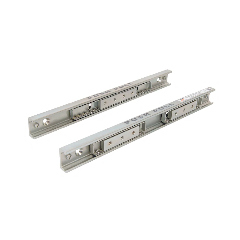
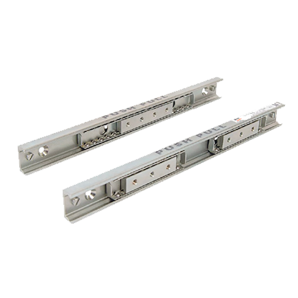
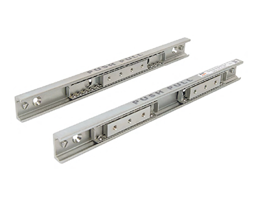
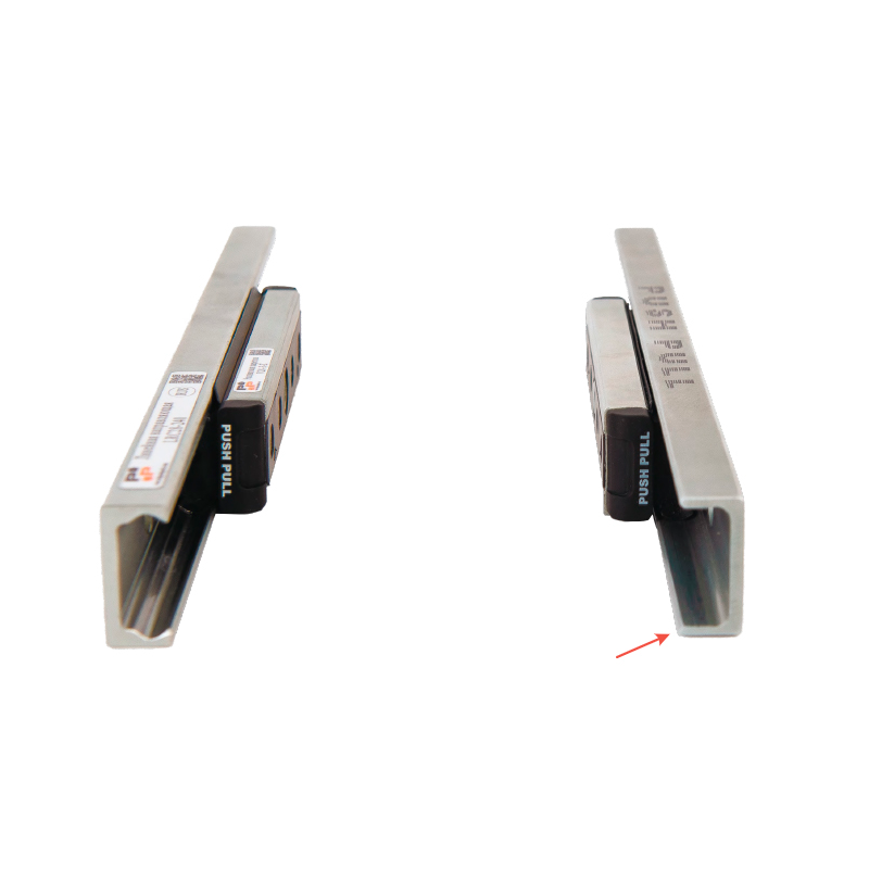
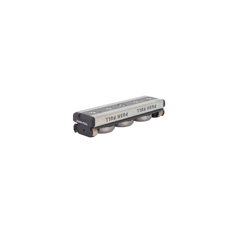
Cold-drawn steel C-profile. System includes a linear guide with a C-profile with one or more sliders moving in a ball cage. This series has the highest load capacity of PUSH PULL products.

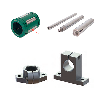
Bushing design allows to compensate angular deviation up to 0.5° between shaft and bushing axes. Position repeatability and accuracy of the raceways of metal inserts and balls allows to achieve a higher load capacity in the same standard size compared to other bushings.
| Code | Load capacity, kg/m | Tolerance, h6 μm | Hardering depth | fx45°, mm |
| LC12-1000-h6 | 0.89 | -11 | ≥0.8 | 0.5 |
| LC12-2000-h6 | ||||
| LC12-3000-h6 |
| Code | Load capacity, kg/m | Tolerance, h6 μm | Hardering depth | fx45°, mm |
| LC16-1000-h6 | 1.58 | -11 | ≥1.5 | 0.5 |
| LC16-2000-h6 | ||||
| LC16-3000-h6 | ||||
| LC16-4000-h6 |
| Code | Load capacity, kg/m | Tolerance, h6 μm | Hardering depth | fx45°, mm |
| LC20-1000-h6 | 2.47 | -13 | ≥1.5 | 1 |
| LC20-2000-h6 | ||||
| LC20-3000-h6 | ||||
| LC20-4000-h6 |
| Code | Load capacity, kg/m | Tolerance, h6 μm | Hardering depth | fx45°, mm |
| LC30-1000-h6 | 5.55 | -13 | ≥2 | 1 |
| LC30-2000-h6 | ||||
| LC30-3000-h6 | ||||
| LC30-4000-h6 |
| Code | Load capacity, kg/m | Tolerance, h6 μm | Hardering depth | fx45°, mm |
| LC40-1000-h6 | 9.87 | -16 | ≥2.5 | 1 |
| LC40-2000-h6 | ||||
| LC40-3000-h6 | ||||
| LC40-4000-h6 |
| Code | Load capacity, kg/m | Tolerance, h6 μm | Hardering depth | fx45°, mm |
| LC50-1000-h6 | 15.4 | -16 | ≥2.5 | 1 |
| LC50-2000-h6 | ||||
| LC50-3000-h6 | ||||
| LC50-4000-h6 |
| Code | Diameter of shaft ⌀ d, mm | Row of balls | Cmin, H | Cmax, H | C0min, H | C0max, H |
| C12-S-2W | 12 | 5 | 1020 | 1397 | 1290 | 1870 |
| Code | Diameter of shaft ⌀ d, mm | Row of balls | Cmin, H | Cmax, H | C0min, H | C0max, H |
| C16-S-2W | 16 | 5 | 1250 | 1712 | 1550 | 2278 |
| Code | Diameter of shaft ⌀ d, mm | Row of balls | Cmin, H | Cmax, H | C0min, H | C0max, H |
| C20-S-2W | 20 | 6 | 2090 | 2549 | 2630 | 3340 |
| Code | Diameter of shaft ⌀ d, mm | Row of balls | Cmin, H | Cmax, H | C0min, H | C0max, H |
| C30-S-2W | 30 | 6 | 5470 | 6673 | 6810 | 8716 |
| Code | Diameter of shaft ⌀ d, mm | Row of balls | Cmin, H | Cmax, H | C0min, H | C0max, H |
| C40-S-2W | 40 | 6 | 6590 | 8039 | 8230 | 10534 |
| Code | Diameter of shaft ⌀ d, mm | Row of balls | Cmin, H | Cmax, H | C0min, H | C0max, H |
| C50-S-2W | 50 | 6 | 10800 | 13176 | 13500 | 17280 |
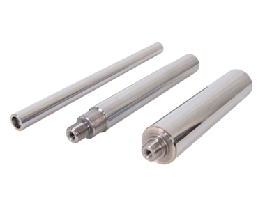
| Code | Diameter, mm | Weight, g |
| SS12 | 12 | 30 |
| SSF12 | 12 | 20 |
| Code | Diameter, mm | Weight, g |
| SS16 | 16 | 40 |
| SSF16 | 16 | 27 |
| Code | Diameter, mm | Weight, g |
| SS20 | 20 | 70 |
| SSF20 | 20 | 40 |
| Code | Diameter, mm | Weight, g |
| SS30 | 30 | 180 |
| SSF30 | 30 | 110 |
| Code | Diameter, mm | Weight, g |
| SS40 | 40 | 420 |
| SSF40 | 40 | 510 |
| Code | Diameter, mm | Weight, g |
| SS50 | 50 | 750 |
| SSF50 | 50 | 890 |

A trapezoidal threaded screw and trapezoidal nut. Flange nuts are made of bronze or wear-resistant polyurethane. Lead screws are made of carbon steel.
Discontinued.
Only repeat orders without changes to the previously delivered configuration.
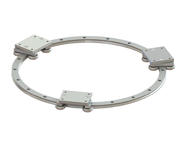
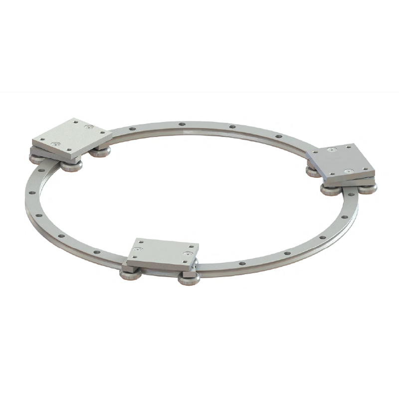
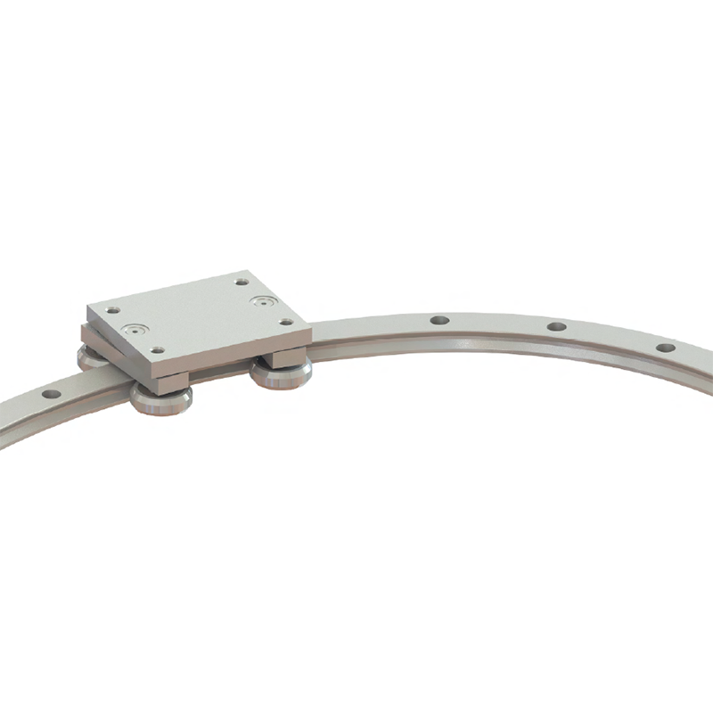
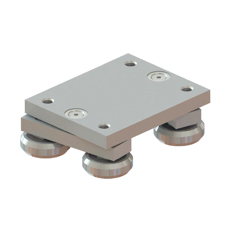
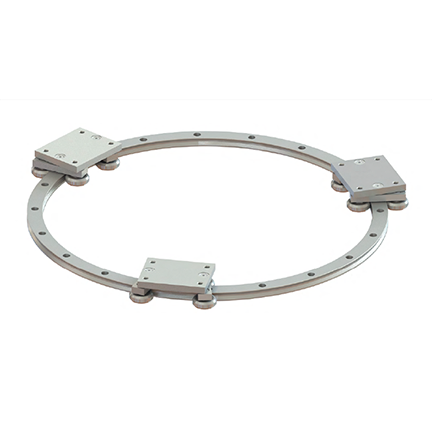
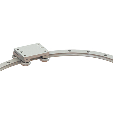
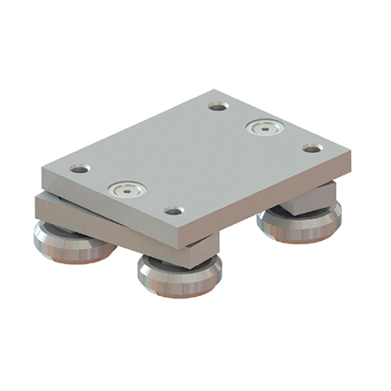
Guides of this series are designed to move the load along a curvilinear path. Guides are customized to meet specific requirements, allowing unique solutions to be created.